 | –≠–ª–µ–∫—Ç—Ä–æ–Ω–Ω—ã–π –∫–æ–º–ø–æ–Ω–µ–Ω—Ç: YSS915 | –°–∫–∞—á–∞—Ç—å:  PDF PDF  ZIP ZIP |
YAMAHA CORPORATION
YSS915
CATALOGUE No:LSI-4SS915A2
1999.09
YSS915
Karaoke Processor 2 for Video disc player
(KP2V2)
INTRODUCTION
YSS915 (KP2V2) is an LSI for processing Karaoke voice signals.
This LSI has an A/D converter (1 channel) for the microphone echo, and a memory for the microphone echo and
key control. These features allow achieving the functions needed for the Karaoke system by using only one LSI
chip. As for the microphone echoes, many other types of echoes are available in addition to ordinary ones so that
YSS915 is applicable to various uses.
In addition to these Karaoke programs, YSS915 is able to provide the Movie & Music programs, with which the
surround effect is applied to the movie and music sources for giving the users more enjoyment.
YSS915 is pin compatible with and register compatible with YSS903 (KP2V).
FEATURES
[
[
[
[ Fundamental Functions ]
Fundamental Functions ]
Fundamental Functions ]
Fundamental Functions ]
1)
Karaoke program
∑
Key Control (Control by 50 cents in +/- 600 cent range, +/- one octave, etc.)
∑
Voice Cancel
Microphone Echo
∑
Normal microphone echo (174 msec or less (fs = 44.1 kHz))
∑
Stereo-Echo/ Reverb-Echo
∑
Microphone Key Control (+/- 10 cents, +/- 20 cents, +/- 400 cents, +/- 700 cents and +/- 1 octave)
∑
Microphone "YMERSIONTM"
Tone Control
∑
Bass, Mid-tone, Treble (0 to +/- 10 dB at 2 dB steps)
Surround
∑
"YMERSIONTM" (Yamaha's original wide surround technology)
2)
Movie and music program
Surround
∑
Initial reflection sound synthesizing system
∑
Yamaha "YMERSIONTM"
Tone Control
∑
Bass, Mid-tone, Treble (0 to +/- 10 dB at 2 dB steps)
[
[
[
[ I/O Interface ]
I/O Interface ]
I/O Interface ]
I/O Interface ]
∑
Digital signal inputs
: 2 channels (16/18/20/24 bits)
∑
Digital signal outputs
: 2 channels (16/18/20/24 bits)
∑
Analog signal input
: 1 channel ( for the microphone )
∑
Microprocessor interface : Serial four line system
∑
Through-mode
: Digital input is outputted without any processing
(Correspond with fs = 96 kHz 24 bit DVD format)
[
[
[
[
Others
Others
Others
Others
]
]
]
]
∑
Pin/register upper compatible with YSS903 (KP2V)
∑
Sampling frequency
: 32, 37.8, 44.1, 48 kHz or correspond with 96 kHz through-mode.
∑
Package
: 28 pin SOP ( YSS915-M )

YSS915
2
Difference between YSS903 and YSS915
1. No built-in DAC.
(Refer to the process flow chart in "OPERATIONS".)
2. Connectable directly with MSB justified data output ADC.
(Refer to "Format 4" of "4. Digital audio interface" in " FUNCTIONS".)
3. Microphone interface terminals CDI and CDO can be connected on the board.
This feature allows to reduce the number of ports by one.
(Refer to "5. Microcomputer interface" in " FUNCTIONS".)
4. Input fader has been added for the microphone echo.
This feature allows to apply fade-in/fade-out control to the microphone echo through designation with
one bit from the microcomputer.
(Refer to "1. Karaoke program" in " OPERATIONS", and "3) VCR ($02)" of "1. Functions" in
"REGISTERS".)
5. Zero level detection function has been added for digital audio output.
YSS915 outputs "0" at the pin "ZERO" when an audio input has been zero for a certain period.
This signal can be used to improve S/N ratio by muting the output of external DAC.
(Refer to "6. Others" in " FUNCTIONS".)
6. An output port PO has been added for controlling peripheral devices.
The port "PO" can be used, as an example, to control the gain of audio output amplifier through this
LSI from the microcomputer.
(Refer to "6. Others" in " FUNCTIONS".)
7. A mode with extended band width for microphone echo has been newly added.
Two types of cut-off frequency have been added for the low pass filter.
(Refer to "7) RVR ($06)" and "11) MDR ($1C)" of "1. Functions" in "REGISTERS".)
8.
Internal DSP has been given the operation accuracy of 20 bits.
Internal multiplier-accumulator become 20bit*13bit=24bit therefore overall bit accuracy become
improved from 18bit(YSS903) to 20bit(YSS915).
In through-mode which internal DSP is not used for processing the accuracy of input data is
maintained to output.
YSS915
3
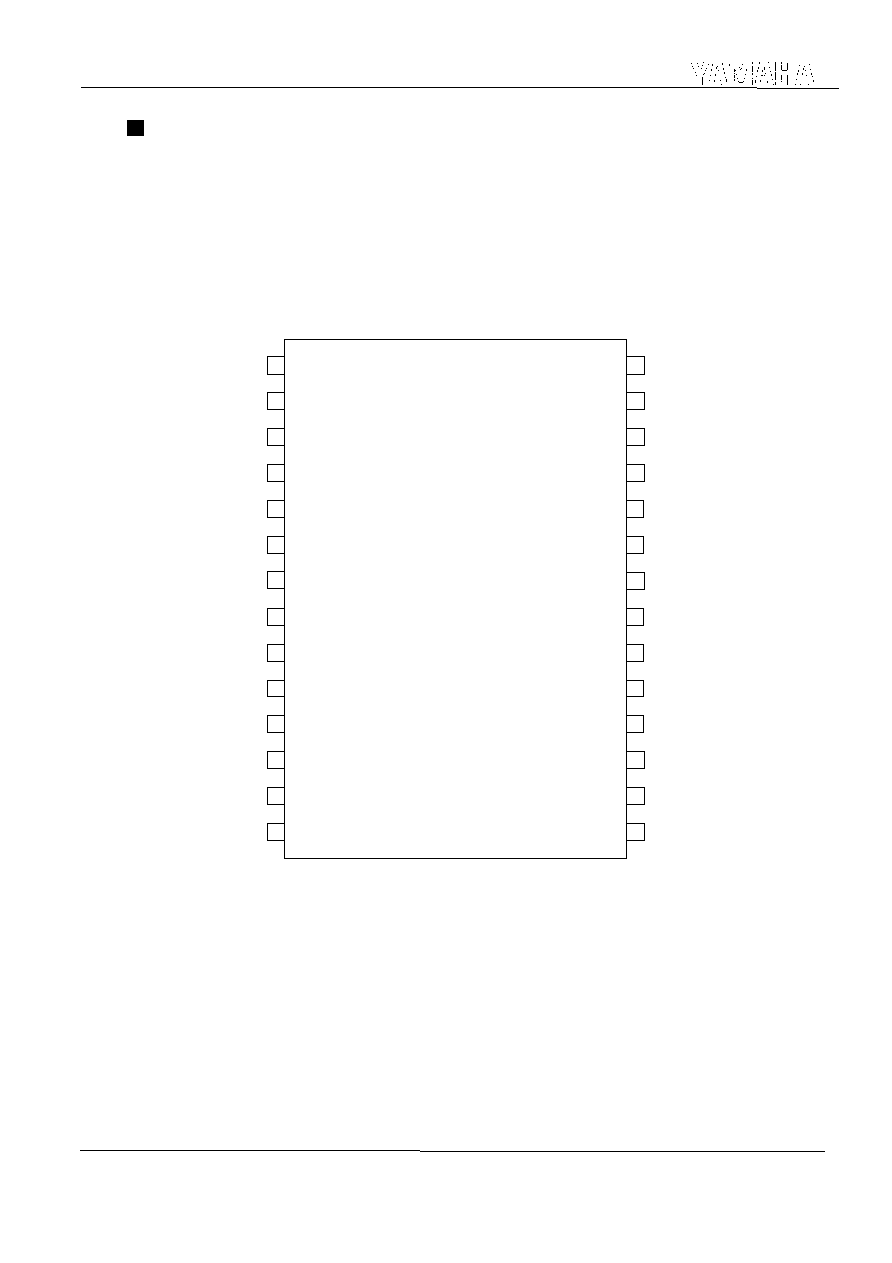
PIN CONFIGURATION
< 28pin SOP Top View >
/IC
/CS
CDI
/SCK
SDSY
DI
BCI
DO
L/R
AOL
VREF
AVSS
AVDD
XI
AOR
DVDD2
DVSS2
BCO
DEPI
DVSS1
DVDD1
ADC1
ADC2
MICIN
CDO
PLLC
P0
1
2
3
4
5
6
7
8
9
10
11
14
12
13
XISEL/ZERO
28
27
26
25
24
23
22
21
20
19
18
17
16
15
YSS915
4
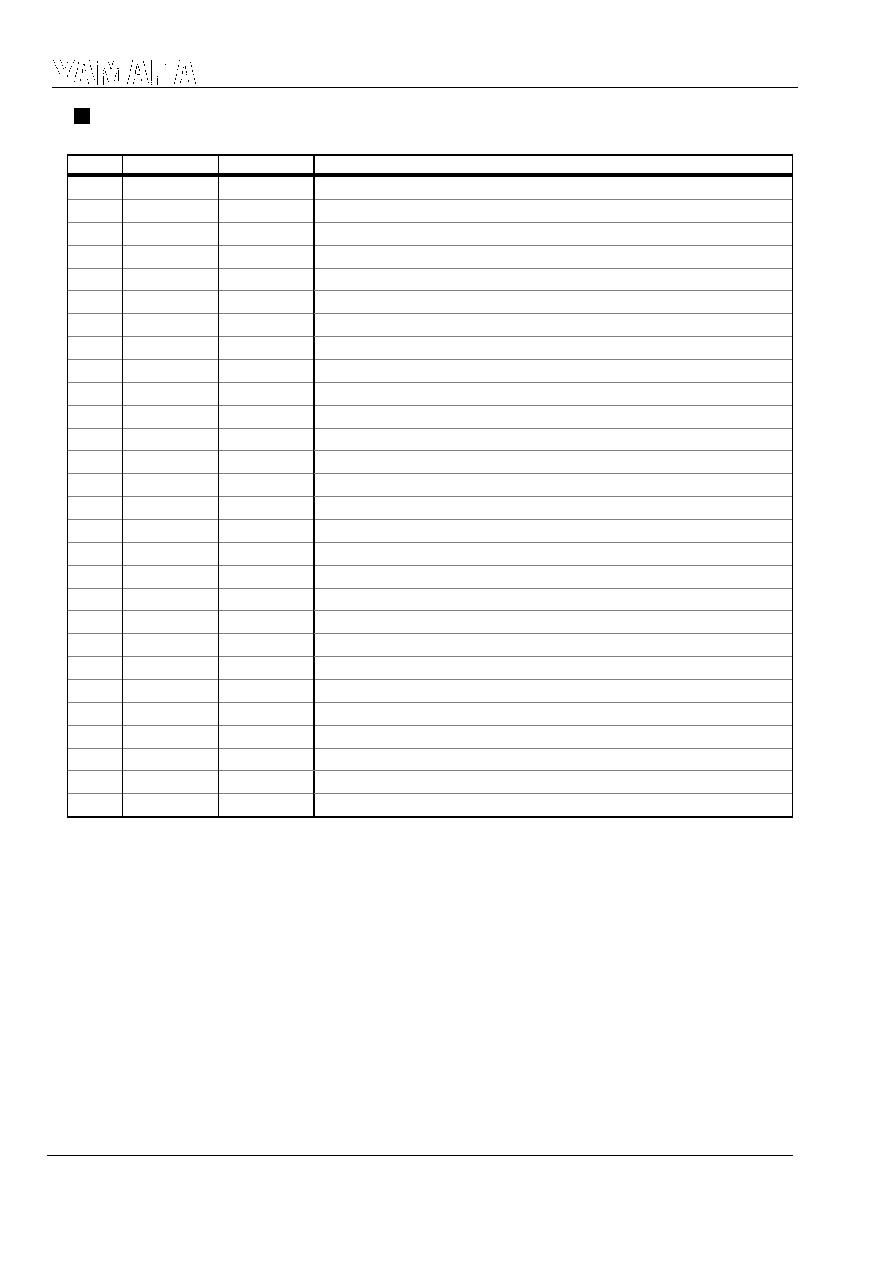
PIN FUNCTION
Notes ;
+ : Pull up
A : Analog terminal
No.
Name
I/O
(See Note1)
Function
1
DI
I+
Digital audio input Serial data
2
BCI
I+
Digital audio input Bit clock
3
DO
O+
Digital audio output Serial data
4
L/R
O
Digital audio output Word clock
5
DVDD1
-
Power supply, +5 V (for digital system)
6
BCO
O
Digital audio output Bit clock
7
DVSS1
-
Ground (for digital system)
8
AVDD
-A
Power supply, +5 V (for analog system)
9
PLLC
-A
Connecting resistor and capacitor for PLL
10
AVSS
-A
Ground (for analog system)
11
ADC1
-A
Connecting capacitor for ADC
12
ADC2
-A
Connecting capacitor for ADC
13
VREF
OA
Referential voltage output
14
MICIN
IA
Analog input, analog voice signal for microphone channel
15
AOL
OA
Outputs analog voice signal for L channel
16
AOR
OA
Outputs analog voice signal for R channel
17
XI
I
External clock input
18
/IC
I
Initial clear (Low active)
19
DVDD2
-
Power supply, +5 V (for digital system)
20
DEPI
I
De-emphasis control (H : On, L : Off)
21
DVSS2
-
Ground (for digital system)
22
XISEL/ZERO
I+/O
Switches master clock rate/ZERO output
23
P0
I+/O
Test input terminal /P0 output
24
/CS
I
Microcomputer interface input Chip select
25
/SCK
I
Microcomputer interface input Serial clock
26
CDI
I
Microcomputer interface input Serial data
27
CDO
O+
Microcomputer interface output Serial data
28
SDSY
I+
Digital audio input Word clock
YSS915
5
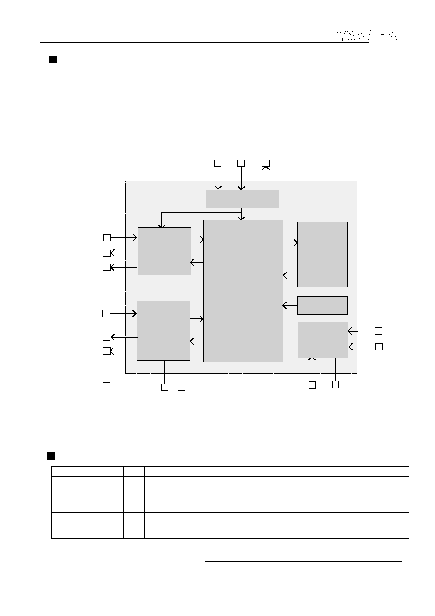
BLOCK DIAGRAM
This LSI has two input channels (L and R) and two output channels (L and R) for digital audio interface. It also has a
one bit Delta-Sigma type AD converter 1 channel (microphone) that performs Delta-Sigma modulation at its analog
block, and decimation/interpolation of 128 times at its DSP.
Karaoke audio signal is processed by DSP for processing Karaoke audio signal and RAM for delay.
For the details of Karaoke audio signal processing, please refer to "OPERATIONS".
The parameters of this LSI are set through CPU interface. For the details of the parameters, please refer to
"REGISTERS".
MODES
Name of mode
Code
Description
KP2
standard mode
N
The functions of KP2 (YSS216B) can be used. The registers are compatible, except that
the coefficient registers (addresses $27 and $30 to $33) of KP2 that controls the analog
audio input and analog microphone echo output cannot be used because YSS903 does not
have these ports.
KP2V
extended mode
E Every function of this device can be used.
Analog block
DSP
for delay
RAM
Digital I/O
Interface
CPU interface
Clock
generator
Program ROM
DEPI
CDI
/SCK
SDSY,DI,BCI
DO,L/R,BCO
AOL
AOR
XI
XISEL
VREF
/IC
CDO
P0
ADC1
MICIN
PLLC
ADC2
ZERO
KP2V2
/CS