
Obsolescence Notice
This product is obsolete.
This information is available for your
convenience only.
For more information on
Zarlink's obsolete products and
replacement product lists, please visit
http://products.zarlink.com/obsolete_products/

THIS DOCUMENT IS FOR MAINTENANCE
PURPOSES ONLY AND IS NOT
RECOMMENDED FOR NEW DESIGNS
FEATURES
Low Power Consumption (1.5mA)
Single Chip Solution
Guaranteed 100MHz Operation
Exceptionally Stable RSSI
APPLICATIONS
Cellular Radio Telephones
Cordless Telephones
QUICK REFERENCE DATA
Supply Voltage 2.5V to 7 5V
Sensitivity 3
�
V
Co-Channel Rejection 7dB
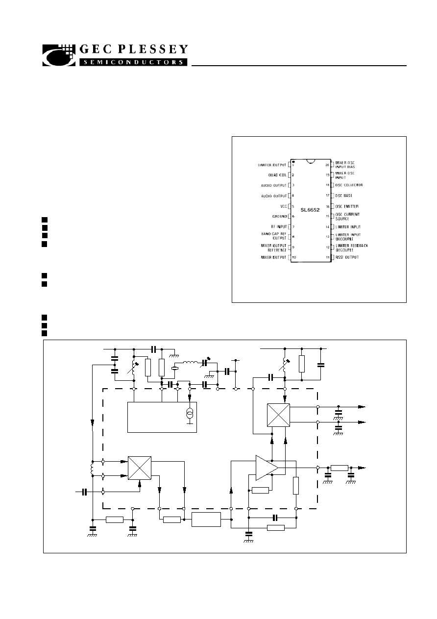
SL6652
LOWER POWER IF/AF CIRCUIT (WITH RSSI) FOR FM CELLULAR RADIO
The SL6652 is a complete single chip mixer/oscillator, IF
amplifier and detector for FM cellular radio, cordless
telephones and low power radio applications. It features an
exceptionally stable RSSI (Received Signal Strength
Indicator) output using a unique system of detection. Supply
current is less than 2mA from a supply voltage in the range
2.5V to 7.5V.
Fig. 1 Pin connections (top view)
DP20
DG20
MP20
Fig. 2 block diagram
DS 3285 -1
VCC
33p
270p
33k
33k
1n
8p2
10�
20 - 40p
0V
220n
VCC
VCC
330p
39k
10p
OSCILLATOR
INPUT
200mV
RMS
RFC
MIXER
INPUT
3�V
1n
10n
10k
100n
+1.2V
LOAD
RESISTOR
1.5k
CERAMIC
FILTER
220n
1.5k
(TO MATCH FILTER)
220n
10n
100n
RSSI
1k
270p
270p
AUDIO
OUTPUTS
100mV RMS
(3kHz DEVIATION)
DETECTOR
1�A
3
4
11
RSSI
200k
12
13
14
200k
IF AMP
20k
10
9
8
BIAS
7
20
19
+15dB (ADJUSTABLE)
100MHz MAX
8�A
2k
8�A
1k
MIXER
C
B
E
OSCILLATOR
TRANSISTOR
0V
SL6652
+90dB (LIGHTING)
1.5MHz MAX
50�A
40k
40k
2
1
5
6
15
16
17
18
X1
8p2
SL6652 IS FOR MAINTENANCE PURPOSES ONLY AND IS NOT RECOMMENDED FOR NEW DESIGNS
SL6652
ABSOLUTE MAXIMUM RATINGS
Supply voltage
8V
Storage temperature
-55
�
C to +150
�
C
Operating temperature
-55
�
C to +125
�
C
Mixer input
1V rms
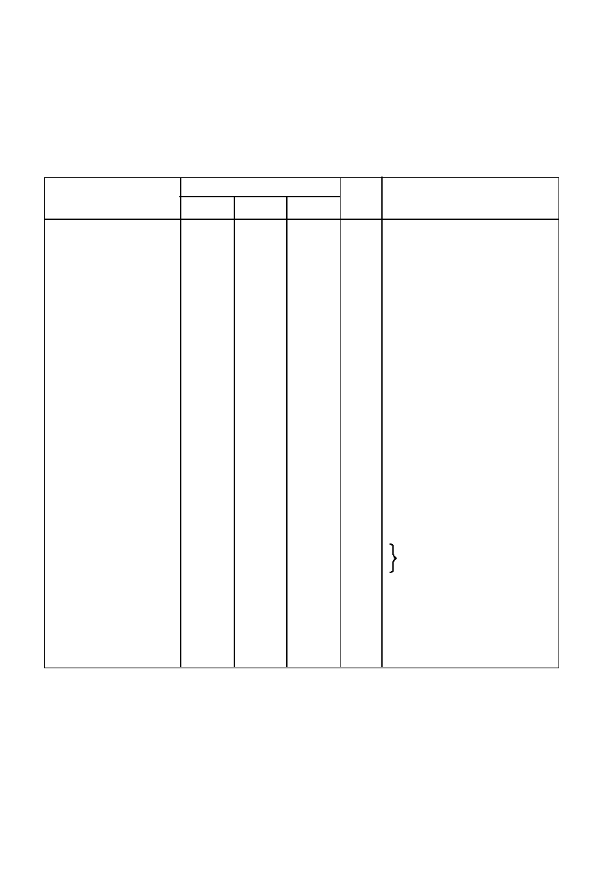
ELECTRICAL CHARACTERISTICS
Test conditions (unless otherwise stated):
V
CC
= 2.5V to 7.5V, T
amb
= -30
�
C to +85
�
C, IF = 455kHz, RF = 50MHz, Quad Coil Working Q = 30
NOTES
1. The RSSI output is 100% dynamically tested at 5V and +20
�
C over a 70dB range. First the input to pin 14 is set to
2.5mV and the RSSI current recorded Then for each step of 10dB from -40 to +30dB the current is measured again. The
current change in each step must meet the specified figure for current change. The RSSI output is guaranteed monotonic
and free from discontinuities over this range.
2. Co-channel rejection is measured by applying a 3kHz deviation, 1 kHz modulated signal at an input level to give a 20dB
SINAD ratio. Then a 3kHz deviation, 400Hz modulated signal on the same frequency is also applied and its level increased
to degrade the SINAD to 14dB.
Typ.
1.5
5
3
40
1.2
7
1
2
5
15
-10
500
90
1500
20
60
0.5
40
65
1.22
Min.
1.0
180
100
40
30
455
75
50
0.9
70
Value
Characteristics
Units
Conditions
Overall
Supply current
Sensitivity
AM rejection
V
bias
Co-channel rejection
Mixer
RF input impedance
OSC input impedance
OSC input bias
Mixer gain
3rd order input intercept
OSC input level
OSC frequency
Oscillator
Current sink
H
fe
f
T
IF Amplifier
Gain
Frequency
Diff. input impedance
Detector
Audio output level
Ultimate S/N ratio
THD
Output impedance
Inter-output isolation
RSSI Output (T
amb
= +25
�
C)
Output current
Output current
Current change
Linear dynamic range
Max.
2.0
10
1.4
300
70
125
5
20
80
1.5
mA
�
V
�
V
dB
V
dB
kohm
kohm
�
A
dB
dBm
mV
MHz
�
A
MHz
dB
kHz
kohm
mV
dB
%
kohm
dB
�
A
�
A
�
A/dB
dB
20dB SINAD
12dB SINAD
RF input <500
�
V
T
amb
= 25
�
C
See Note 2
At V
bias
Rload = 1.5k
T
amb
= 25
�
C
40 ... 70
�
A
40 ... 70
�
A
5mV into pin 14
1kHz
No input pin 14
Pin 14 = 2.5mV
See Note 1
See Note 1
SL6652
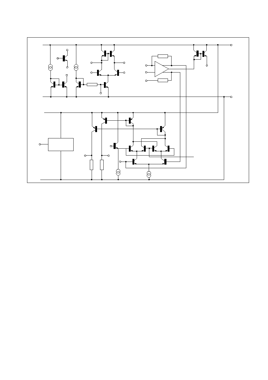
Fig. 3 Internal schematic
GENERAL DESCRIPTION
The SL6652 is a very low power, high performance
integrated circuit intended for IF amplification and
demodulation in FM radio receivers. It comprises:
q
A mixer stage for use up to lOOMHz
q
An uncommitted transistor for use as an oscillator
q
A current sink for biasing this transistor
q
A limiting amplifier operating up to 1.5MHz
q
A quadrature detector with differential AF output
q
An RSSI (Received Signal Strength Indicator) output
Mixer
The mixer is single balanced with an active load. Gain is
set externally by the load resistor although the value is
normally determined by that required for matching into the
ceramic filter. It is possible to use a tuned circuit but an
increase in mixer gain will result in a corresponding reduction
of the mixer input intercept point.
The RF input is a diode-biased transistor with a bias
current of typically 300
�
A. The oscillator input is differential
but would normally be driven single-ended. Special care
should be taken to avoid accidental overload of the oscillator
input.
Oscillator
The oscillator consists of an uncommitted transistor and a
separate current sink. The user should ensure that the design
of oscillator is suitable for the type of crystal and frequency
required; it may not always be adequate to duplicate the
design shown in this data sheet.
IF amplifier
The limiting amplifier is capable of operation to at least 1
MHz and the input impedance is set by an external resistor to
match the ceramic filter. Because of the high gain, pins 12 and
13 must be adequately bypassed.
Detector
A conventional quadrature detector is fed internally from
the IF amplifier; the quadrature input is fed externally using an
appropriate capacitor and phase shift network. A differential
output is provided to feed a comparator for digital use,
although it can also be used to provide AFC.
RSSI output
The RSSI output is a current source with value
proportional to the logarithm of the IF input signal amplitude.
There is a small residual current due to noise within the
amplifier (and mixer) but beyond this point there is a measured
and guaranteed 70dB dynamic range. The typical range
extends to 92dB, independent of frequency, and with
exceptionally good temperature and supply voltage stability.
18
16
17
15
9
20
10
19
7
4k
13
14
12
200k
200k
11
5
6
8
3
BAND-GAP
REFERENCE
4
2
1
40k
40k
BIAS