GENERAL DATA
Life Expectancy
Minimum operations
Mechanical
1 x 10
8
operations at 3 Hz
Electrical
2 x 10
5
operations at 0.5 A,
125 VAC, resistive
5 x 10
5
operations at 1.0 A,
30 VDC, resistive
Operate Time (typical)
2 ms at nominal coil voltage
Release Time (typical)
1 ms at nominal coil voltage
(with no coil suppression)
Bounce (typical)
1 ms (at 10 mA contact current)
Capacitance
< 1.5 pF open and adjacent contacts
< 2.0 pF contact to coil
Dielectric Strength
See table
(at sea level)
Insulation Resistance
10
9
ohms min. at 500 VDC
Dropout
Greater than 10% of nominal coil voltage
Ambient Temperature
At nominal coil voltage
Operating
-40∞C (-40∞F) to 85∞C (185∞F)
Storage
-40∞C (-40∞F) to 115∞C (239∞F)
Vibration
Operational, 3.3 mm DA, 10 - 55 Hz
Maximum, 5.5 mm DA, 10 -55 Hz
Shock
Operational, 50g min., 11 ms
Maximum, 100 g min., 6 ms
Enclosure
LCP
Terminals
Tinned copper alloy, P.C.
Max. Solder Temp.
See charts
Max. Solder Time
See charts
Max. Solvent Temp.
80∞C (176∞F)
Max. Immersion Time
30 seconds
Weight
1.8 grams
CONTACTS
Arrangement
DPDT (2 Form C)
Bifurcated crossbar contacts
Ratings
Non-inductive load:
Max. switched power: 60 W or 62.5 VA
Max. switched current: 2 A
Max. switched voltage: 220 VDC or 250 VAC
Rated Load
0.5 A at 125 VAC res.
UL/CSA
2.0 A at 30 VDC res.
0.3 A at 110 VDC res.
Material
Silver alloy; gold clad
Resistance
< 50 milliohms initially at 6 V, 0.1 A
COIL
Power
At Pickup Voltage
AZ849: 79 mW to 169 mW
(typical)
AZ849P1: 57 mW to 85 mW
AZ849P2: 110 mW to 170 mW
Max. Continuous
826 mW at 20∞C (68∞F) ambient
Dissipation
652 mW at 40∞C (104∞F) ambient
Temperature Rise
At nominal coil voltage
18∞C (32∞F) (3 - 12 VDC coils)
25∞C (45∞F) (18, 24 VDC coils)
34∞C (61∞F) (48 VDC coils)
Temperature
Max. 115∞C (239∞F)
AZ849
11/3/99W
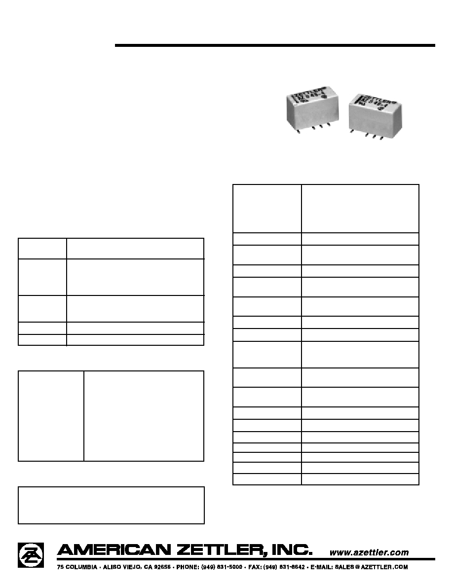
MICROMINIATURE SURFACE
MOUNT POLARIZED RELAY
FEATURES
∑ High dielectric and surge voltage: 2.5 kV surge
(per Bellcore TA-NWT-001089), 1.5 kV surge
(per FCC Part 68), 1,000 VRMS open contacts
∑ Low power consumption: 56 mW set
∑ Non-latching and latching versions
∑ Single coil and dual coil versions
∑ Stable contact resistance for low level signal switching
∑ Epoxy sealed for automatic wave soldering and cleaning
∑ UL E43203; CSA 73363
∑ All plastics meet UL94 V-0, 30 min. oxygen index
NOTES
1. All values at 20∞C (68∞F).
2. Relay may pull in with less than "Must Operate" value.
3. Relay has fixed coil polarity.
4. Specifications subject to change without notice.
AZ849
11/3/99W
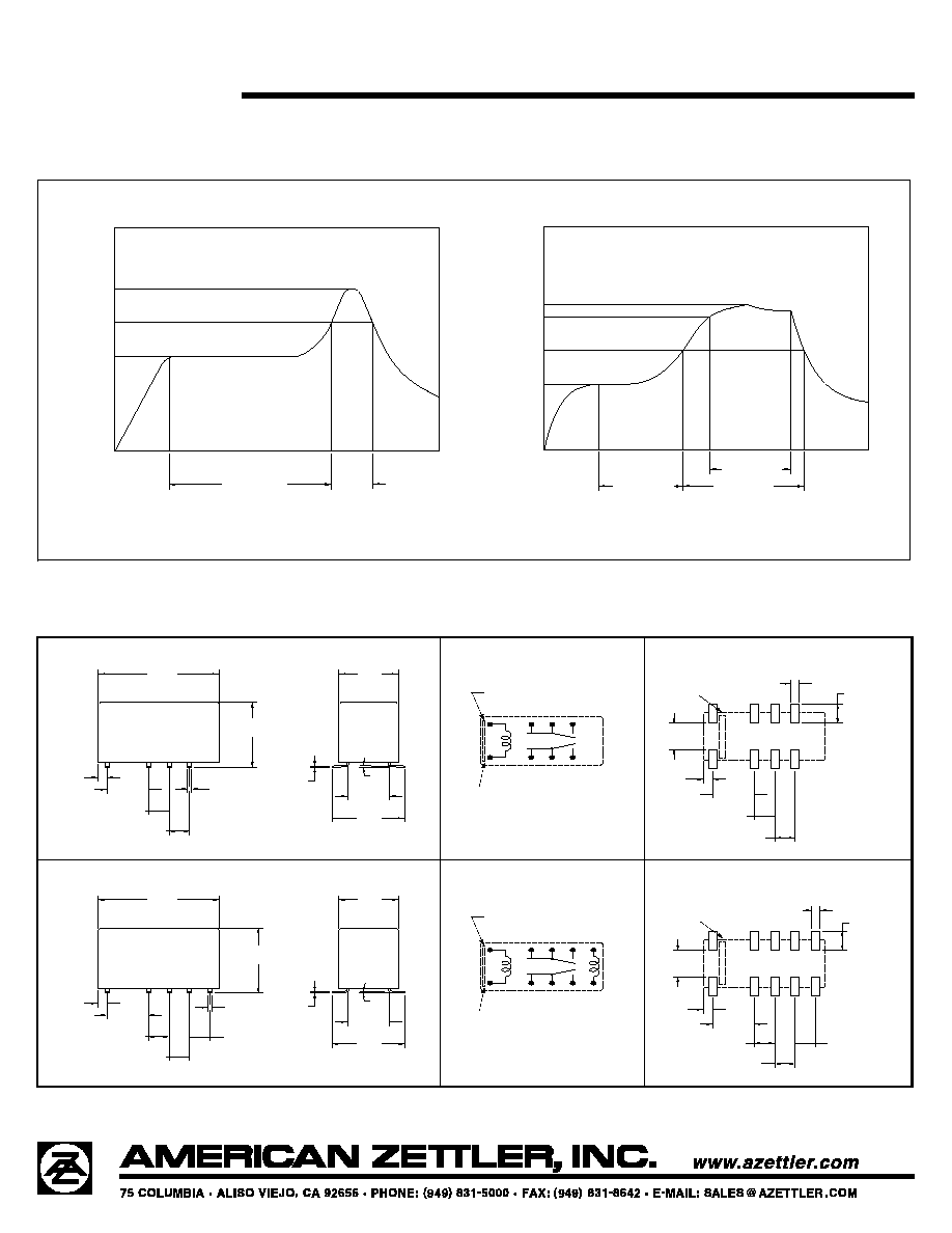
SOLDERING DATA
1
T
T
T2
3
PREHEATING
SOLDERING
COOLING
TEMPERATURE (∞C)
IRS (Infrared Reflow Soldering)
MAX
30 SEC
120 SEC MAX
MECHANICAL DATA
COOLING
3
T
215∞C MAX
T2
T 1
PREHEATING
VPS (Vapor Phase Soldering)
SOLDERING
TEMPERATURE (
∞
C)
60 SEC MAX
60 SEC MAX
90 SEC MAX
VIEWED TOWARDS TERMINALS
PC BOARD LAYOUT
.020
[0.5]
.043
[1.1]
.200
.100
[2.54]
[5.08]
.100
[2.54]
[14.9]
[5.08]
.354
[9.0]
.200
DEENERGIZED OR RESET CONDITION
ORIENTATION MARK
[7.4]
4 X .160
[4.08]
.043
[1.1]
.587
.394
[10.0]
.008
[0.2]
9
10
4
3
8
5
(+)
(-)
(-)
(+)
12
1
[1.0]
[5.08]
.100
[2.54]
.100
[2.54]
.200
8 X .116
[2.94]
8 X .040
.291
VIEWED TOWARDS TERMINALS
WIRING DIAGRAMS
PC BOARD LAYOUT
WIRING DIAGRAMS
10 X .040
[1.0]
VIEWED TOWARDS TERMINALS
3∑
TYP
.100
[2.54]
.020
[0.5]
.200
[5.08]
.043
[1.1]
.100
[2.54]
.100
[2.54]
.200
[5.08]
.354
[9.0]
DEENERGIZED OR RESET CONDITION
VIEWED TOWARDS TERMINALS
ORIENTATION MARK
5 X .160
[4.08]
.043
[1.1]
.394
[10.0]
.587
[14.9]
.008
[0.2]
5
6
9
10
8
7
(-)
(+)
1
.291
[7.4]
12
.100
[2.54]
.200
[5.08]
.100
[2.54]
.100
[2.54]
10 X .116
[2.94]
(-)
(+)
3
4
Reset Set
Set
Reset
Stripe on top of relay indicates location of pins 1 and 10.
Stripe on top of relay
indicates location of
pins 1 and 10.
Stripe on top of relay
indicates location of
pins 1 and 10.
Stripe on top of relay indicates location of pins 1 and 10.
T
3= 245 ∞C MAX
T
2= 200 ∞C MAX
T
1= 165 ∞C MAX
T
3= 200 ∞C MAX
T
2= 165 ∞C MAX
T
1= 100 ∞C MAX
Dimensions in inches with metric equivalents in parentheses. Tolerance: ±0.010"