STARTER KIT DATASHEET FOR ST625X AND ST626X
October 2000
1/4
This is advance information from STMicroelectronics. Details are subject to change without notice.
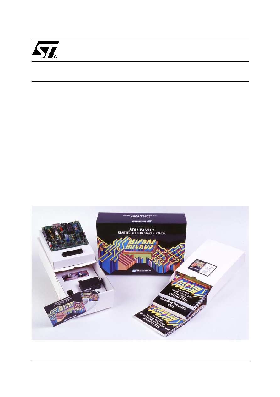
ST626XC-KIT
STARTER KIT
FOR ST625x and ST626x MCUs
HARDWARE FEATURES
s
Immediate evaluation of all ST625x and ST626x
devices, with demonstration examples.
s
Software debugging within the user's real appli-
cation environment.
s
In-Socket Programming of all EPROM and OTP
ST625x and ST626x (DIP packages).
s
In-Circuit programming of all EPROM and OTP
ST625x and ST626x devices on the user's ap-
plication board (all packages).
SOFTWARE FEATURES
s
Software simulator including I/O read/write.
s
Assembler, linker, debugger.
s
OTP and EPROM programming utilities.
s
Application examples and demonstrations.
635
2/4
ST626XC-KIT
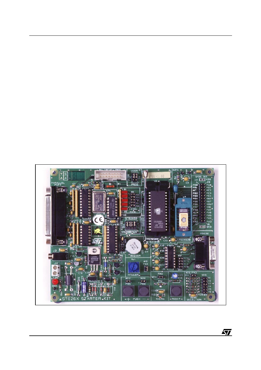
The Starter Kit Board
The Starter Kit board includes the following re-
sources:
�
Reset and data control buttons.
�
LED indicators.
�
Resistance trimmer.
�
Analog to digital converter.
�
Audio transducer circuit.
�
RS-232 interface.
�
Demonstration program selector jumpers.
It comes with its own power supply unit that can be
plugged into an AC mains source, or a DC source
with the following characteristics:
�
Voltage: 16V min./20V max.
�
Current: 100 mA min.
It includes the following connectors:
�
A parallel port connector (P1) for connection to
the host PC when it is used as a hardware sim-
ulator or for programming.
�
A remote resource I/O interface connector (J2)
to which you can connect your own hardware
resource.
�
An RS-232 connector, which you can use for
observing RS-232 communication control
using an ST6.
�
A connector for your own in-circuit ST6 pro-
gramming board.
636
3/4
ST626XC-KIT
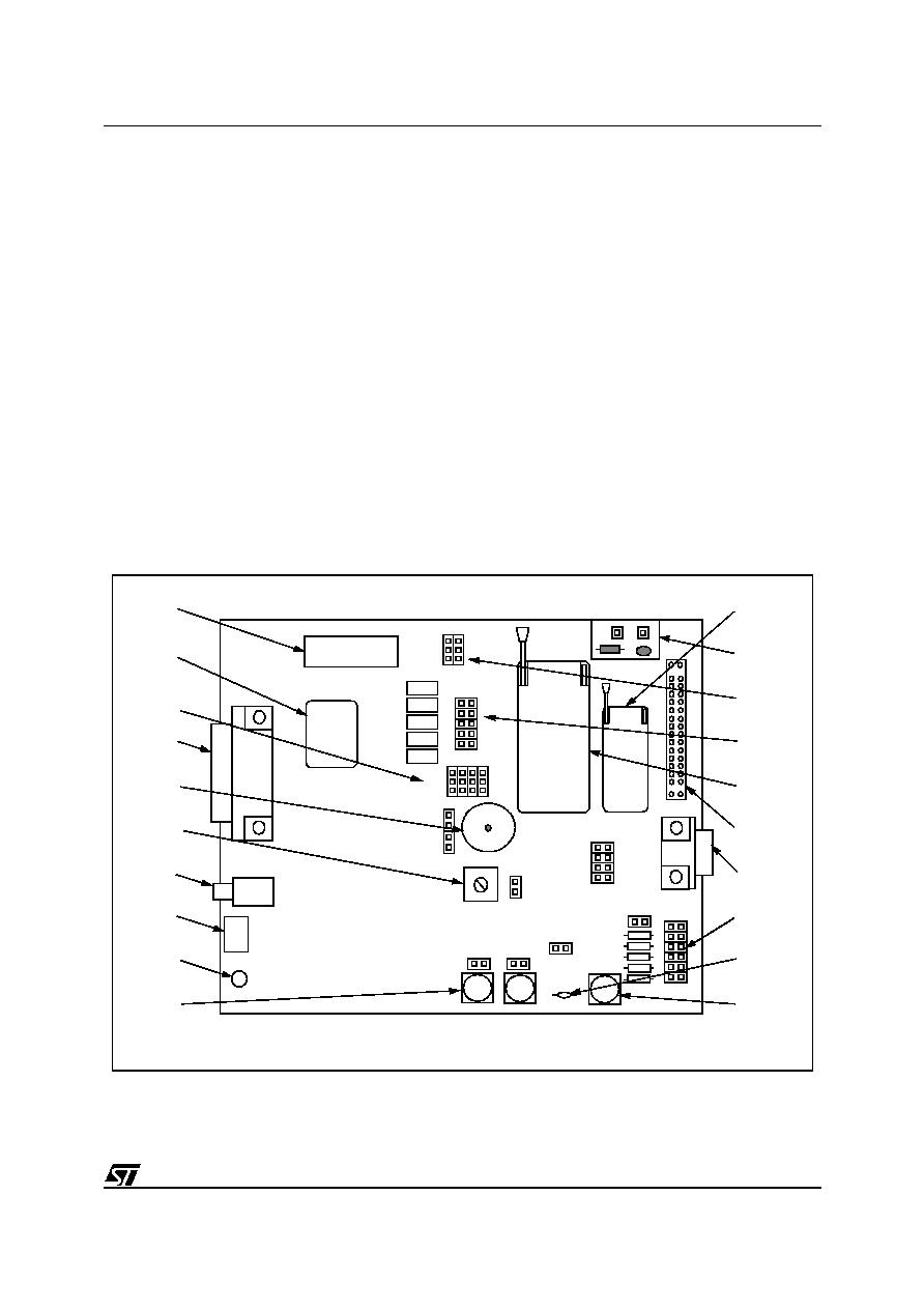
The following diagram shows the layout of the Starter Kit board.
1
In-circuit programming connector (J1).
20
DIL-16 ZIF MCU socket
2
8 Mhz Oscillator.
19
Digital to analog conversion circuit.
3
"ST6260/62" or "ST6265" device
selection jumpers W10 to W13.
18
"Programming" or "User" operating mode
selection jumpers W1 and W2.
4
PC connector P1.
17
Five LED level indicators including jumpers
W4 to W8.
5
Audio Transducer circuit.
16
DIL 20-28 ZIF MCU socket.
6
10 K
trimmer.
15
Remote resource I/O interface connector J2.
7
Power supply JACK connector J3.
14
RS232 interface circuit and connector.
8
Power supply connector J4.
13
Demonstration routine selector.
9
Power supply LED indicator LD6.
12
Thermistor including jumper W24.
10
"+" and "-" buttons.
11
RESET button.
1
2
3
4
5
6
7
8
9
W4
W18
W22
W26
W17
W1
W
W24
W15
10
+
-
W2
W23
W25
W21
W31
13
W
10
20
19
18
17
16
15
14
13
12
11
637
4/4
ST626XC-KIT
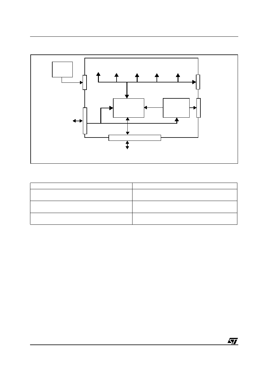
Figure 1. Block Diagram of the Starter Kit board
�
ORDERING INFORMATION
Information furnished is believed to be accurate and reliable. However, STMicroelectronics assumes no responsibility for the consequences
of use of such information nor for any infringement of patents or other rights of third parties which may result from its use. No license is granted
by implication or otherwise under any patent or patent rights of STMicroelectronics. Specifications mentioned in this publication are subject
to change without notice. This publication supersedes and replaces all information previously supplied. STMicroelectronics products are not
authorized for use as critical components in life support devices or systems without the express written approval of STMicroelectronics.
The ST logo is a registered trademark of STMicroelectronics
�
2000 STMicroelectronics - All Rights Reserved.
Purchase of I
2
C Components by STMicroelectronics conveys a license under the Philips I
2
C Patent. Rights to use these components in an
I
2
C system is granted provided that the system conforms to the I
2
C Standard Specification as defined by Philips.
STMicroelectronics Group of Companies
Australia - Brazil - China - Finland - France - Germany - Hong Kong - India - Italy - Japan - Malaysia - Malta - Morocco - Singapore - Spain
Sweden - Switzerland - United Kingdom - U.S.A.
http://www.st.com
UNIT
POWER
SUPPLY
PARALLEL CONNECTION
TO PC AND
SOFTWARE SIMULATOR
IN-CIRCUIT
PROGRAMMING
J1
RS232
P2
USER APPLICATION
ST626x I/O CONNECTION
ST62E65
J3
J4
P1
EPROM
PROGRAMMER
DAC
THERMISTOR
LEDs
TRIMMER
J2
TRANSDUCER
Sales Type
Description
ST626XC-KIT/UK
Starter Kit for ST625x and ST626x MCUs for
operation in United Kingdom
ST626XC-KIT/US
Starter Kit for ST625x and ST626x MCUs for
operation from 110 Vac mains
ST626XC-KIT/EU
Starter Kit for ST625x and ST626x MCUs for
operation from 220 Vac mains
638